[:en]
Surfaçage de plaque martyr
Use face milling cutters
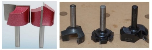
Surface milling cutters are used to generate a planar surface perpendicular to the axis of rotation of the milling cutter.
They are very well suited to surface a spoilboard and to correct defects of parallelism and flatness.
The size of the martyr plate must not be greater than the maximum working surface of the machine.
Refer to your machine’s documentation for theses dimensions.
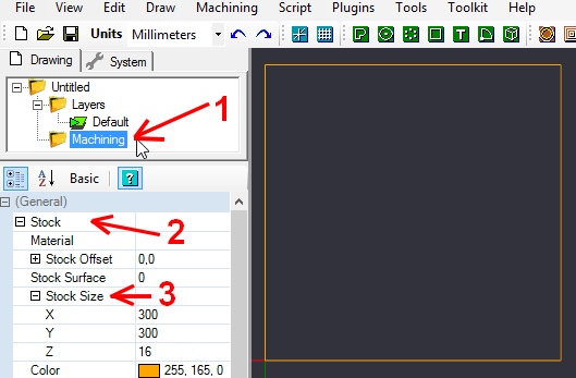
A) Indicate the dimensions of the spoilboard
To do this, click on the folder « machining » and then choose the stock size
Reminder : the size of the spoilboard in X and Y must correspond to the maximum move of the machine (working area)
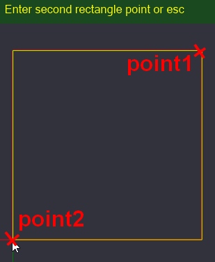
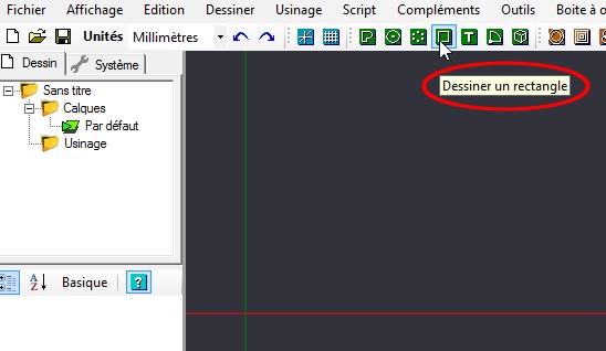
B) Draw the boundary of the area to be surfaced
To do this, use the drawing icon (icons in green) « draw a rectangle »
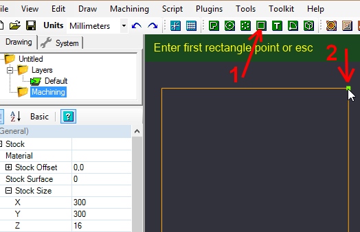
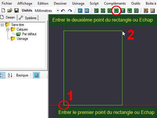
Place the construction points of the rectangle at the bottom left and top right corners of the spoilboard in brown
With this way the zone to be surfaced will correspond to the total surface of the martyr plate.
C) Choose « Pocket » machining
A surfacing is the equivalent of machining an open pocket
See the article on the strategy of machining the pockets to know the difference between closed pocket and open pocket.
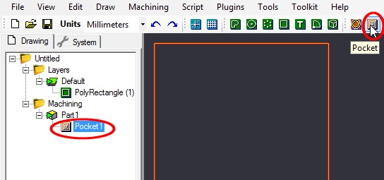
To do this, select the rectangle previously draw and click on the pocket icon.
A « Pocket » icon will appear under the machining folder and below « Part1« , click on it to set the machining.
D) Configuring pocket machining
One surfacing pocket have theirs features :
– a very low machining depth because it is only necessary to eliminate the flatness defects or the traces of the previous machining operations.
– the tool must pass over a very large area.
So, a relatively large tool diameter of 20 mm or more is used and a feed rate high enough to prevent the surfacing taking too long.
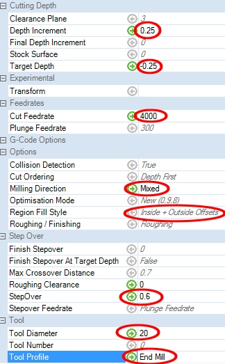
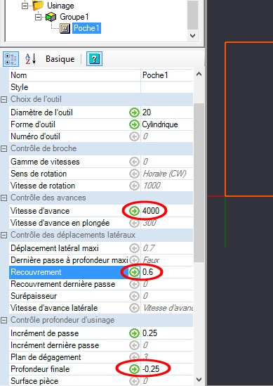
In this example :
The tool have diameter of 20mm
Feed rate is high: 4000 mm / min
The depth of machining is very low: 0.25mm
The step over is 0.6 or 60%, it’s a compromise between the surface quality and the time required for machining.
For more information on the StepOver rate see the article dedicated to the this subject
For the choice of machining direction, consult the dedicated article
Conventional or climb milling direction
For region fill style you can leave the default setting « Internal + Outside Offset« .
If you want another style, more information is available in
article on the strategy of machining the pockets
E) Creation of toolpaths and check of machining traces
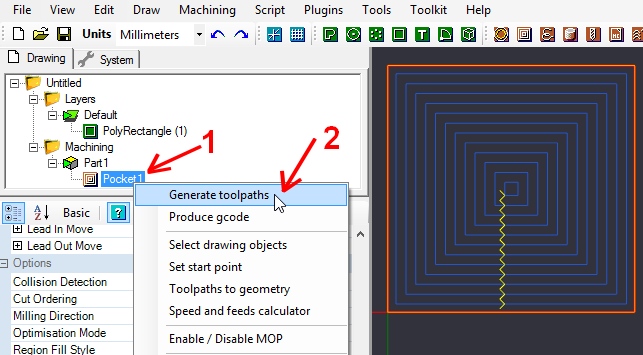
After each change of machining parameter and before the creation of the Gcode you must generate the toolpaths
by right-clicking on the machining.
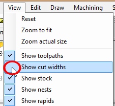
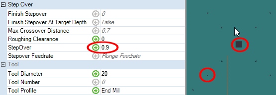
It is useful after generating the toolpaths to check the option « Show Cut Width » in the « View » menu
In this example, you can see with 90% StepOver, there is some unmachined material in the middle and in the angles at the change of direction.
It is necessary to reduce the StepOver rate, for example to 0.8 or 0.7, then regenerate the toolpaths and check the cutting widths.
F) To ensure that the surfacing is carried out perfectly including around the plate
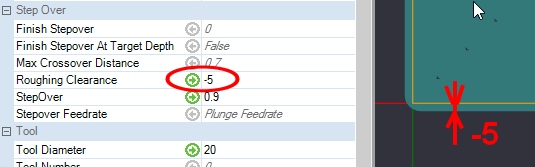
In the section « Step Over »
You can indicate a negative value, so the tool will slightly overhang the surface.
G) Creating the Gcode
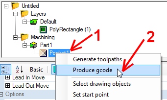
The last step is to create the Gcode by right clicking on the machining
Then « Create gcode »
You can give a name to your Gcode file before the extension « nc » and save it in the « Gcode » folder of the SD card of your smoothiebox.
Also save your CAMBAM file on your computer by doing « File —> save as« , this will be useful for your future spoilboard, especially if you want to change some settings without having to do it again.
A ) Modeling spoilboard
In Fusion 360 can modeling directly in 3D before machining.
The spoilboard is a parallelepiped, so start modeling a parallelepipedic volume.
You can follow there links below, it’s lesson in chinese
– Présentation of fusion 360 software
– Install fusion 360
– Création of parallélépipède with Fusion 360
To know more about use Fusion 360 can see the youtube chanel of Taiwan designer Channelbox MAYA
https://www.youtube.com/watch?v=BAHkGNsh4iE&list=PLZJ2lSlFhOX0x71u1YVgUFaWuet_Cf2aF
B) Possibly give an appearance to spoilboard
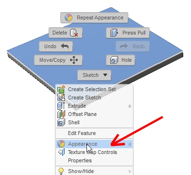
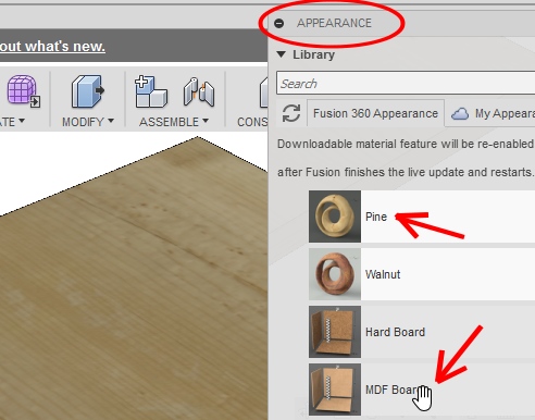
For more realism you can choose an appearance, for example pine wood or MDF..
For this you have to right click when the mouse pointer is on the plate and choose « Appearance »
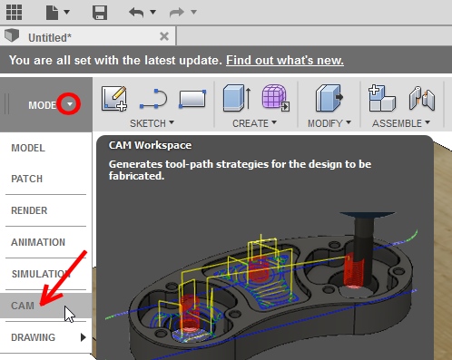
C) Switch from the modeling module to the machining preparation module
D) Start a machining configuration
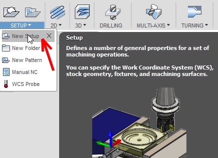
To do this, you must select « Setup » and then « New Setup »
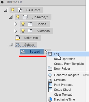
A folder setup will be created in the « Browser » that it is placed under the history of modeling.
By right-clicking on the setup created it is possible to remodify each configuration parameter
E) Select the point of origin and orientation of the work coordinate system
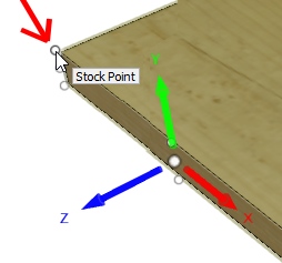
To conform to the origin point set in the Formosa CNC, choose an origin at the top left corner.
The Z axis is misaligned to match the architecture of the machine it would have to be vertical.
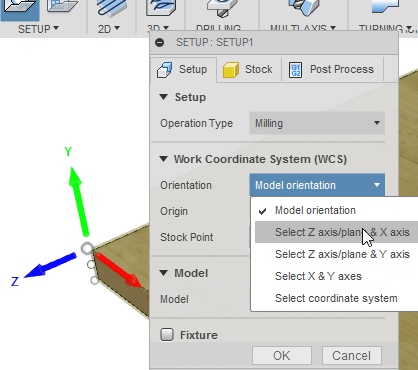
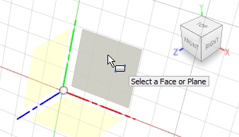
So go the « Model orientation » of the WCS and choose a selection of the Z and X axes.
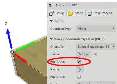
If one of the axes has a wrong direction it is possible to check the box « Flip »
Note :
If you want to directly have the WCS properly oriented when you switch into the CAM module, it is necessary to do the design thinking about the machine.
For exemple, design first sketch in XY plane and extrude along Z axis.
Because the spindle move along the Z axis.
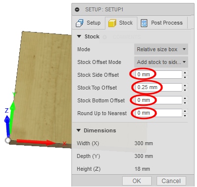
The case of sploilboard surfacing is particular because the dimensions of the sploilboard are the same as those of the final part in X and Y.
For the Z dimension a very small part of material will be removed like 0.25mm
It is therefore necessary to set « 0 » to all offset except 0.25mm for « Stock Top Offset.
The spoilboard will be of the same size as the finished object machined for X and Y and only 0,25mm will be removed during the surfacing operation.
G) Add the surface machining operation
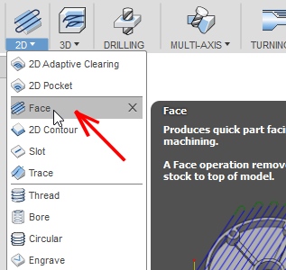
Choice of tool
Choose the tool according to the type of operation (mark 2), and choose Face (Mark 3)
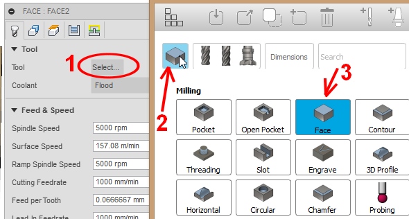
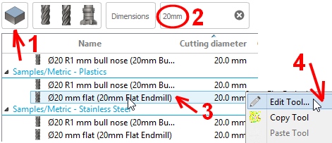
You can filter by diameter for example 20mm
Then choose from the list a cutter for plastic or wood with flat end.
And then to fit your tool right click « Edit Tool »
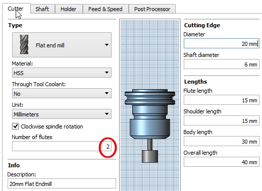
You can modify some parameters such as the number of teeth of the tool and the feed rate.
For other parameters if you do not have a spindle drive, if you do not have an ATC system with an automatic tool magazine, it is not worth changing them.
The Formosa CNCs are designed to be as simple to use as possible and there is no MCS (machine coordinate system) or tool offset recording as for machines used in the industry.
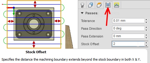
Setting an offset around the surface to be machined
To be sure that the outer limit of spoilboard will bee surfaced you can add an offset (offset)
To do this, go to the « Passes » tab and then enter a value in the « Stock Offset » part (2 mm in the example below)
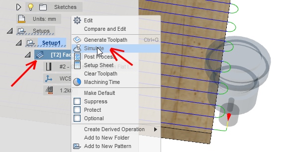
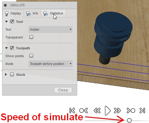
G) Simulate machining
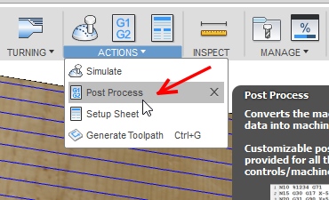
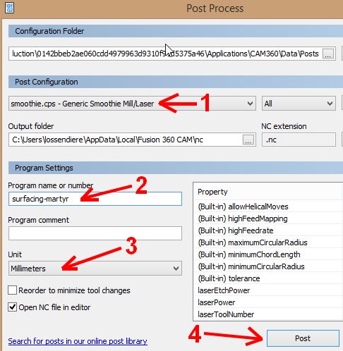
H) Creating the Gcode
1 Commentaire
Surfaçage de plaque martyr
Use face milling cutters
Surface milling cutters are used to generate a planar surface perpendicular to the axis of rotation of the milling cutter.
They are very well suited to surface a spoilboard and to correct defects of parallelism and flatness.
The size of the martyr plate must not be greater than the maximum working surface of the machine.
Refer to your machine’s documentation for theses dimensions.
A) Indicate the dimensions of the spoilboard
To do this, click on the folder « machining » and then choose the stock size
Reminder : the size of the spoilboard in X and Y must correspond to the maximum move of the machine (working area)
B) Draw the boundary of the area to be surfaced
To do this, use the drawing icon (icons in green) « draw a rectangle »
Place the construction points of the rectangle at the bottom left and top right corners of the spoilboard in brown
With this way the zone to be surfaced will correspond to the total surface of the martyr plate.
C) Choose « Pocket » machining
A surfacing is the equivalent of machining an open pocket
See the article on the strategy of machining the pockets to know the difference between closed pocket and open pocket.
To do this, select the rectangle previously draw and click on the pocket icon.
A « Pocket » icon will appear under the machining folder and below « Part1« , click on it to set the machining.
D) Configuring pocket machining
One surfacing pocket have theirs features :
– a very low machining depth because it is only necessary to eliminate the flatness defects or the traces of the previous machining operations.
– the tool must pass over a very large area.
So, a relatively large tool diameter of 20 mm or more is used and a feed rate high enough to prevent the surfacing taking too long.
In this example :
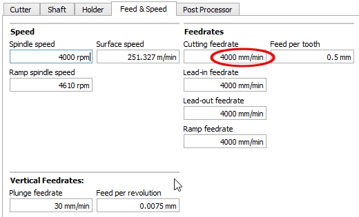
The tool have diameter of 20mm
Feed rate is high: 4000 mm / min
The depth of machining is very low: 0.25mm
The step over is 0.6 or 60%, it’s a compromise between the surface quality and the time required for machining.
For more information on the StepOver rate see the article dedicated to the this subject
For the choice of machining direction, consult the dedicated article
Conventional or climb milling direction
For region fill style you can leave the default setting « Internal + Outside Offset« .
If you want another style, more information is available in
article on the strategy of machining the pockets
E) Creation of toolpaths and check of machining traces
After each change of machining parameter and before the creation of the Gcode you must generate the toolpaths
by right-clicking on the machining.
It is useful after generating the toolpaths to check the option « Show Cut Width » in the « View » menu
In this example, you can see with 90% StepOver, there is some unmachined material in the middle and in the angles at the change of direction.
It is necessary to reduce the StepOver rate, for example to 0.8 or 0.7, then regenerate the toolpaths and check the cutting widths.
F) To ensure that the surfacing is carried out perfectly including around the plate
In the section « Step Over »
You can indicate a negative value, so the tool will slightly overhang the surface.
G) Creating the Gcode
The last step is to create the Gcode by right clicking on the machining
Then « Create gcode »
You can give a name to your Gcode file before the extension « nc » and save it in the « Gcode » folder of the SD card of your smoothiebox.
Also save your CAMBAM file on your computer by doing « File —> save as« , this will be useful for your future spoilboard, especially if you want to change some settings without having to do it again.
A ) Modeling spoilboard
In Fusion 360 can modeling directly in 3D before machining.
The spoilboard is a parallelepiped, so start modeling a parallelepipedic volume.
You can follow there links below, it’s lesson in chinese
– Présentation of fusion 360 software
– Install fusion 360
– Création of parallélépipède with Fusion 360
To know more about use Fusion 360 can see the youtube chanel of Taiwan designer Channelbox MAYA
https://www.youtube.com/watch?v=BAHkGNsh4iE&list=PLZJ2lSlFhOX0x71u1YVgUFaWuet_Cf2aF
B) Possibly give an appearance to spoilboard
For more realism you can choose an appearance, for example pine wood or MDF..
For this you have to right click when the mouse pointer is on the plate and choose « Appearance »
C) Switch from the modeling module to the machining preparation module
D) Start a machining configuration
To do this, you must select « Setup » and then « New Setup »
A folder setup will be created in the « Browser » that it is placed under the history of modeling.
By right-clicking on the setup created it is possible to remodify each configuration parameter
E) Select the point of origin and orientation of the work coordinate system
To conform to the origin point set in the Formosa CNC, choose an origin at the top left corner.
The Z axis is misaligned to match the architecture of the machine it would have to be vertical.
So go the « Model orientation » of the WCS and choose a selection of the Z and X axes.
If one of the axes has a wrong direction it is possible to check the box « Flip »
Note :
If you want to directly have the WCS properly oriented when you switch into the CAM module, it is necessary to do the design thinking about the machine.
For exemple, design first sketch in XY plane and extrude along Z axis.
Because the spindle move along the Z axis.
The case of sploilboard surfacing is particular because the dimensions of the sploilboard are the same as those of the final part in X and Y.
For the Z dimension a very small part of material will be removed like 0.25mm
It is therefore necessary to set « 0 » to all offset except 0.25mm for « Stock Top Offset.
The spoilboard will be of the same size as the finished object machined for X and Y and only 0,25mm will be removed during the surfacing operation.
G) Add the surface machining operation
Choice of tool
Choose the tool according to the type of operation (mark 2), and choose Face (Mark 3)
You can filter by diameter for example 20mm
Then choose from the list a cutter for plastic or wood with flat end.
And then to fit your tool right click « Edit Tool »
You can modify some parameters such as the number of teeth of the tool and the feed rate.
For other parameters if you do not have a spindle drive, if you do not have an ATC system with an automatic tool magazine, it is not worth changing them.
The Formosa CNCs are designed to be as simple to use as possible and there is no MCS (machine coordinate system) or tool offset recording as for machines used in the industry.
Setting an offset around the surface to be machined
To be sure that the outer limit of spoilboard will bee surfaced you can add an offset (offset)
To do this, go to the « Passes » tab and then enter a value in the « Stock Offset » part (2 mm in the example below)
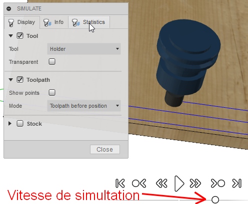
G) Simulate machining
H) Creating the Gcode
1 Commentaire
-
Nom *alf sur 27th avril 2018 à 10:57
merci pour cette explications tres interessante
je vais tester de suite
Surfaçage de plaque martyr
Utilisation de fraises à surfacer ( appelé aussi fraise tourteau )
Les fraises à surfacer permettent de générer une surface plane perpendiculaire à l’axe de rotation de la fraise.
Elles conviennent très bien pour surfacer une plaque martyr et corriger des défauts de parallélisme et planéité.
La taille de la plaque martyr ne doit pas être supérieure à la surface de travail maxi de la machine.
Consultez la documentation de votre machine afin de connaître ses dimensions.
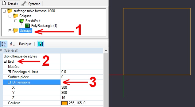
A ) Indiquez les dimensions de la plaque martyr
Pour cela il faut cliquer sur le dossier « usinage » et ensuite choisir les dimensions du brut
Rappel : la taille de la plaque martyr en X et Y devra correspondre au déplacements maxi de la machine (surface de travail)
B ) Tracer la limite de la zone à surfacer
Pour cela utilisez l’icône dessin (icônes en vert) « dessiner un rectangle »
Placez les points de construction du rectangle aux coins inférieur gauche et supérieur droit de la plaque martyr en marron
Ainsi la zone à surfacer correspondra a la surface totale de la plaque martyr.
C ) Choisir l’usinage « Poche »
Un surfaçage est l’équivalent de l’usinage d’une poche ouverte
voir l’article sur la stratégie d’usinage des poches pour connaître la différence entre poche fermée et poche ouverte.
Pour cela, il faut sélectionner le rectangle précédemment dessiné puis cliquer sur l’icône poche.
Une icône « Poche1 » va apparaître dans le dossier usinage et en dessous de « Groupe1« , cliquez dessus afin de paramétrer l’usinage.
D ) Paramétrer l’usinage poche
Une poche de surfaçage à comme caractéristiques :
– une profondeur d’usinage très faible car il s’agit seulement d’éliminer les défauts de planéité ou les traces des usinages précédent.
– d’outil doit passer sur une très grande surface.
Donc on utilise un diamètre d’outil assez important, égal ou supérieur à 20mm et une vitesse d’avance assez élevé pour éviter que le surfaçage prenne trop de temps.
Dans l’exemple ci dessous
L’outil à un diamètre de 20mm
La vitesse d’avance est importante : 4000 mm/min
La profondeur d’usinage est très faible : 0,25mm
Le taux de recouvrement est de 0.6 ou 60% c’est un compromis entre la qualité de surface et le temps nécessaire à l’usinage.
Pour plus d’information sur le taux de recouvrement consultez l’article dédié au taux d’engagement / taux de recouvrement
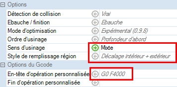
Pour le choix du sens d’usinage, consultez l’article dédié
Usinage en opposition, en avalant ou mixte
Pour le style de remplissage région vous pouvez laisser celui par défaut
c’est à dire « Décalage intérieur + extérieur« .
Si vous souhaitez un autre style, plus d’information sont disponible dans
l’article sur la stratégie d’usinage des poches
E ) Création des parcours d’outil et vérification des traces d’usinage
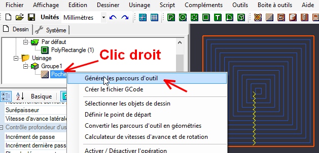
Après chaque changement de paramétrage d’usinage et avant la création du Gcode vous devez générer les parcours d’outil
en faisant un clic droit sur l’usinage.
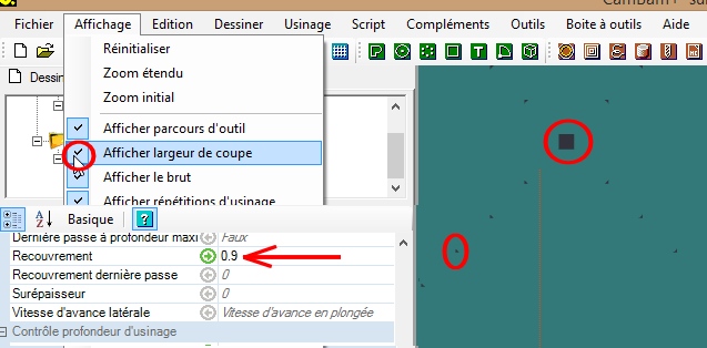
Il est utile après avoir généré les parcours d’outils de cocher l’option « Afficher largeur de coupe » dans le menu « Affichage »
Dans cet exemple on s’aperçois que avec un taux de recouvrement de 90%, il y a un peu de matière non usiné au milieu et dans les angles au changement de direction.
Il faut diminuer le taux de recouvrement par exemple à 0.8 ou 0.7 puis régénérer les parcours d’outils et vérifier les largeurs de coupe.
F ) Pour être sûr que la surfaçage va s’effectuer parfaitement y compris autour de la plaque
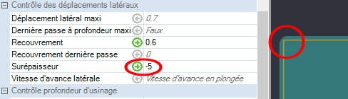
Dans la partie « Contrôle des déplacements latéraux »
vous pouvez indiquer une surépaisseur négative, ainsi la fraise va déborder légèrement de plaque pour surfacer.
G ) Création du Gcode
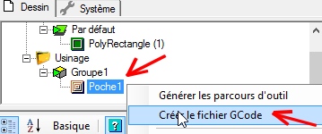
La dernière étape consiste à créer le Gcode en faisant clic droit sur l’usinage
puis « Créer le gcode »
Vous pouvez donner un nom à votre fichier Gcode qui se termine par l’extension « nc » et l’enregistrer dans le dossier « Gcode » de la SD-Card de votre smoothiebox.
Enregistrez aussi votre fichier CAMBAM sur votre ordinateur en faisant « Fichier —> enregistrer sous« , cela vous sera utile lors de vos prochains surfaçages de martyr surtout si vous voulez changer quelques paramétrages sans être obligé de tout refaire.
A ) Modélisation de la plaque martyr
Nous allons afin de s’entraîner pour des usinages plus complexe, préparer le surfaçage à partir d’un modèle 3D
Vous allez donc modéliser au préalable la plaque martyr qui est un simple parallélépidède et suivre les indications des articles
– Présentation du logiciel fusion 360 éventuellement Utiliser Fusion 360 lorsqu’il n’y a plus internet
– Création d’un parallélépipède avec Fusion 360
B ) Eventuellement donnez une apparence à la plaque martyr
Pour plus de réalisme vous pouvez choisir une apparence, par exemple du pin (Pine en Anglais) ou du MDF.
Pour cela il faut faire un clic droit lorsque le pointeur de souris est sur la plaque et choisir « Appearance »
C ) Basculez du module modélisation à celui de préparation d’usinage
D ) Démarrez une configuration d’usinage
Pour cela il faut dans « Setup » puis « New Setup »
Un dossier setup se créer dans le « Browser » celui ci se met en dessous de l’historique de modélisation.
En faisant un clic droit sur le setup ainsi créer il est possible de remodifier chaque paramètre de configuration
E ) Choisir le point d’origine et l’orientation du système de coordonnée de travail
Pour que cela soit conforme au point d’origine paramétré dans la CNC Formosa, il faut choisir une origine au coin supérieur avant gauche.
L’axe Z est mal orienté pour correspondre à l’architecture de la machine il faudrait qu’il soit vertical.
Allez donc le « Model orientation » du WCS et choisissez une sélection de l’axe Z et X.
Si un des axe a une mauvaise direction il est possible de cocher la case « Flip »
Dans l’exemple si contre le sens positif de l’axe Z était vers le bas.
Avec l’option « Flip Z axis » coché il pointe maintenant vers le haut.
Remarque :
Si vous voulez avoir directement le WCS correctement orienté quand vous basculez dans le module CAM, il est nécessaire de faire la conception en pensant à la machine qui va réaliser votre pièce.
F ) Paramétrer le brut
Le cas du surfaçage de plaque martyr est un peu particulier car les dimensions du brut sont les mêmes que celles de la pièce finale en X et Y.
Pour la dimension en Z très peu de matière sera enlevée par exemple 0,25mm
Il faut donc mettre « 0 » à tous les offset sauf 0,25mm pour « Stock Top Offset.
Ainsi le brut sera de la même dimension que l’objet final usiné pour X et Y et seulement 0,25mm sera enlevé lors de l’opération de surfaçage.
G ) Ajouter l’opération d’usinage surfaçage
Choix de l’outil
Choisir l’outil en fonction du type d’opération ( Repère 2 ) et choisir Face ( Repère 3 )
Vous pouvez filtrer par diamètre par exemple 20mm
Ensuite choisir dans la liste une fraise pour plastique ou bois à embout plat.
Et ensuite pour adapter à votre outil faire clic droit « Edit Tool »
Vous pouvez modifier quelques paramètres comme par exemple le nombre de dent de l’outil et la vitesse d’avance.
Pour les autres paramètres si vous n’avez pas de de variateur de broche, si vous n’avez pas de système ATC avec magasin d’outil automatique, cela n’a pas d’intérêt de les changer.
Les CNC Formosa sont conçu pour être les plus simple possible à utiliser et il n’y a pas de système MCS ( repère de coordonnée machine ) ni d’enregistrement de décalage d’outil comme pour les machines utilisées dans l’industrie.
Paramétrage d’un décalage autour de la surface à usiner
Pour être sur que le tour de la plaque martyr soit surfacer vous pouvez ajoutez un décalage ( offset )
Il faut pour cela aller dans l’onglet « Passes » et ensuite entrer une valeur dans la partie « Stock Offset » ( 2 mm dans l’exemple ci-dessous )
G ) Simuler l’usinage
H ) Création du Gcode
1 Commentaire
-
Nom *alf sur 27th avril 2018 à 10:57
merci pour cette explications tres interessante
je vais tester de suite
merci pour cette explications tres interessante
je vais tester de suite