[:en]
Les détecteurs inductifs
The endstop are use for the machine can have reference point, machine origin « 0 »
For endstop it’s common to use SPDT switch (Single Pole Double Throw) more information here
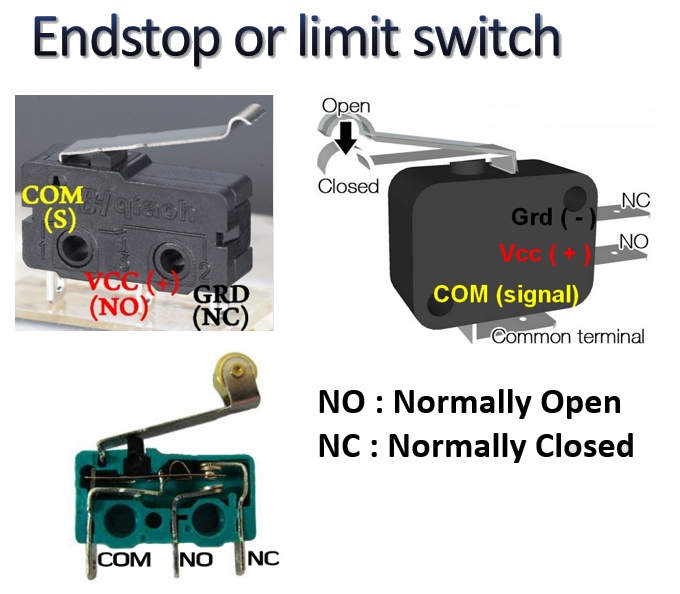
In the official smoothieboard endstop documentation http://smoothieware.org/guide-endstops
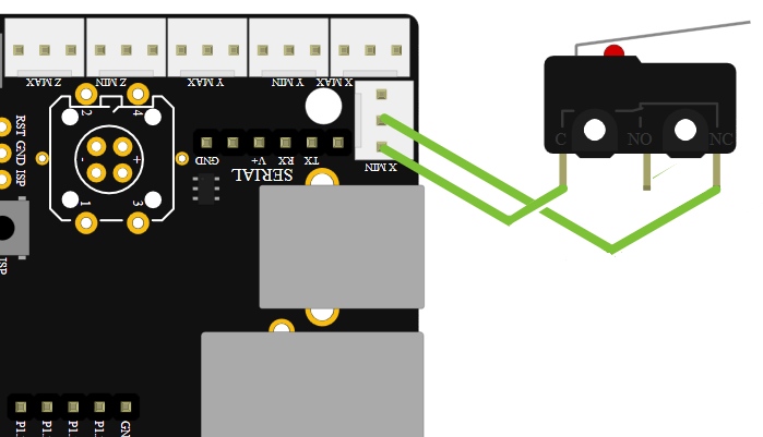
have this drawing and it’s write « Wiring a basic NC endstop »
And when you see your smoothieboard , you can guest when endstop is hit the « O Volt » go to the Signal pin

If you beginner to wiring endstop in input of microcontroler may be you ask at yoursef two question.
– Why use only 2 wire and don’t use 3 wires Ground (-) Signal and VCC (+) ?
- Why the information « O » is send tu input of microcontroller and not « + » ?
The answer or there question are not specific for smoothieboard, the technology use is same when connect switch SPDT or pushbutton in input of electronicboard ( arduino, 3d printer board, etc … )
Why use only 2 wire and don’t use 3 wires Ground (-) Signal and VCC (+) ?
Use 3 wire is Ok, it’s works
– when endstop push, the signal pin of électronic card receive 5Volt to send information « endstop push »
– when endstop don’t hit, the signal pin of électronic receive
0 Volt to send information ‘endstop don’t hit
It’s works, just have 3 small disadvantage
- need buy and prepare more 3 wires if you connect xmin ymin and 7min. 6wires more if you connect endstop min and end stop max.
A little more money and time to prepare - If the red wire (+) breakdown the machine continu to more over the endstop. If the machine is small without very big motor, not damage, but with heavy and strong CNC professional, a simple wire breakdown can be cost a lot of money with damage result.
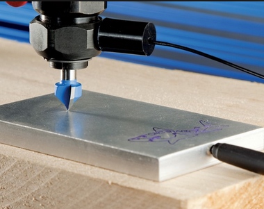
- If you whant connect a touch plate in Zmin, only have 2 location tu connect can’t use the 3 wire.
What need to know when use only 2 wire for connect switch or push button to microcontroler board ?
Below à explain of James Lewis the creator of https://www.baldengineer.com/ and http://addohms.com/ youtube chanel
A pin of input microcontroler board can’t unconnect. If you do this the interference around create sometimes 4,8V; 0,15V 5V… and create fake information inside. That’s why in the video sometimes the LED don’t blink when push button and sometimes blink without push buton. Have somethinks out of control.
The pull up resistor solution explain by James Lewis
Support this guy with buy his DVD if you whant learn électronic because he’s explains are very good
Les détecteurs inductifs
The endstop are use for the machine can have reference point, machine origin « 0 »
For endstop it’s common to use SPDT switch (Single Pole Double Throw) more information here
In the official smoothieboard endstop documentation http://smoothieware.org/guide-endstops
have this drawing and it’s write « Wiring a basic NC endstop »
And when you see your smoothieboard , you can guest when endstop is hit the « O Volt » go to the Signal pin
If you beginner to wiring endstop in input of microcontroler may be you ask at yoursef two question.
– Why use only 2 wire and don’t use 3 wires Ground (-) Signal and VCC (+) ?
- Why the information « O » is send tu input of microcontroller and not « + » ?
The answer or there question are not specific for smoothieboard, the technology use is same when connect switch SPDT or pushbutton in input of electronicboard ( arduino, 3d printer board, etc … )
Why use only 2 wire and don’t use 3 wires Ground (-) Signal and VCC (+) ?
Use 3 wire is Ok, it’s works
– when endstop push, the signal pin of électronic card receive 5Volt to send information « endstop push »
– when endstop don’t hit, the signal pin of électronic receive
0 Volt to send information ‘endstop don’t hit
It’s works, just have 3 small disadvantage
- need buy and prepare more 3 wires if you connect xmin ymin and 7min. 6wires more if you connect endstop min and end stop max.
A little more money and time to prepare - If the red wire (+) breakdown the machine continu to more over the endstop. If the machine is small without very big motor, not damage, but with heavy and strong CNC professional, a simple wire breakdown can be cost a lot of money with damage result.
- If you whant connect a touch plate in Zmin, only have 2 location tu connect can’t use the 3 wire.
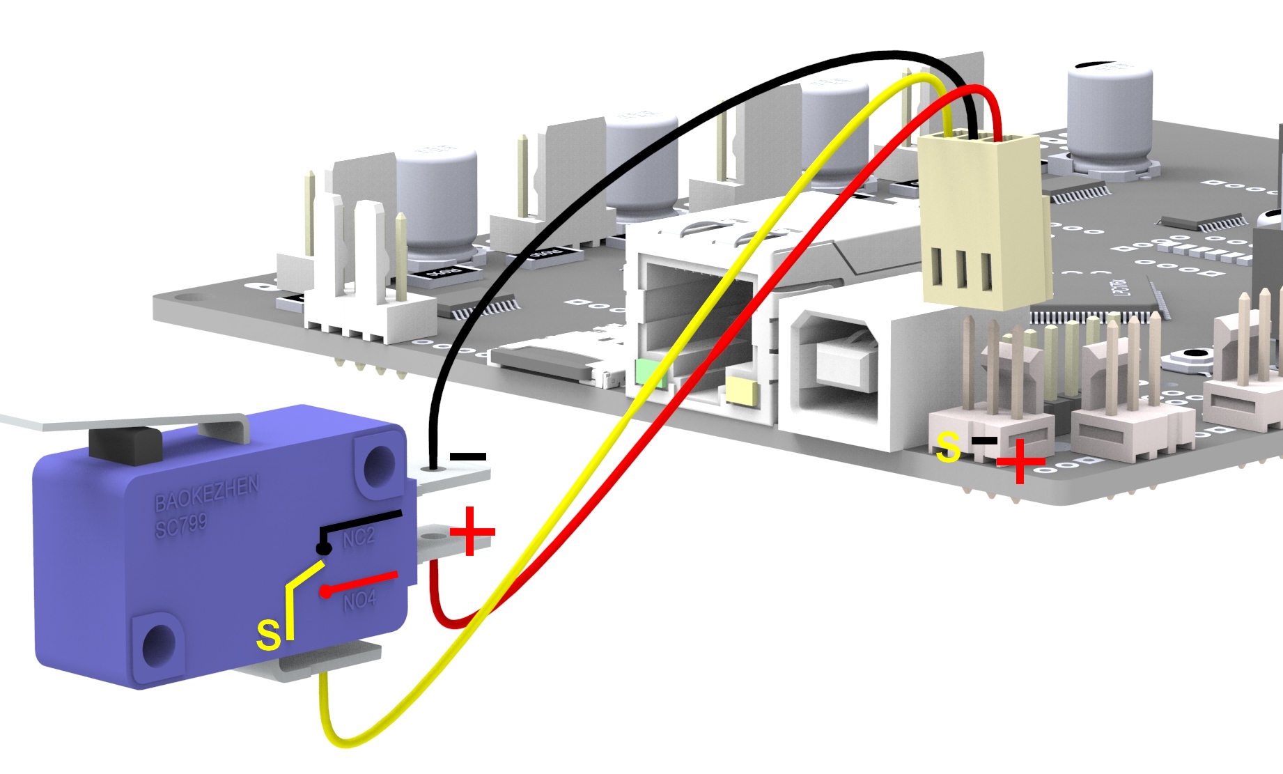
Why use normaly closed endstop and use « 0 » Ground to send the information endstop push ?
For each endstop, it’s better to connect C to Signal and NC to Ground because this means the digital input pin ( endstop connector ) will be connected to Ground in it’s normal state and cut from Ground when the button is pressed. This approach is less prone to noise than the reverse. See here for more information.
Another positive effect of this approach is, that if a wire breaks for some reason you get the same signal as if the endstop is pressed. That makes sure that even with a damaged wire you are not able to overrun the endstop.
What need to know when use only 2 wire for connect switch or push button to microcontroler board ?
Below à explain of James Lewis the creator of https://www.baldengineer.com/ and http://addohms.com/ youtube chanel
A pin of input microcontroler board can’t unconnect. If you do this the interference around create sometimes 4,8V; 0,15V 5V… and create fake information inside. That’s why in the video sometimes the LED don’t blink when push button and sometimes blink without push buton. Have somethinks out of control.
The pull up resistor solution explain by James Lewis
Support this guy with buy his DVD if you whant learn électronic because he’s explains are very good
Explain in Chinese about floating volt level pin and pull up resistor
with Lazy Tomato Lab
See the other vidéo of LazyTomatoLab Chanel http://www.lazytomatolab.com/ very good lesson for learn about Arduino
Important !!
Check that you do not connect VCC ( red ) and GND ( black ) to a mechanical (microswitch) endstop!
Depending on your wiring that may fries your smoothieboard instantly or when the switch gets pressed.
If you’re not careful enough you can damage your board.
The endstop setting section inside config file
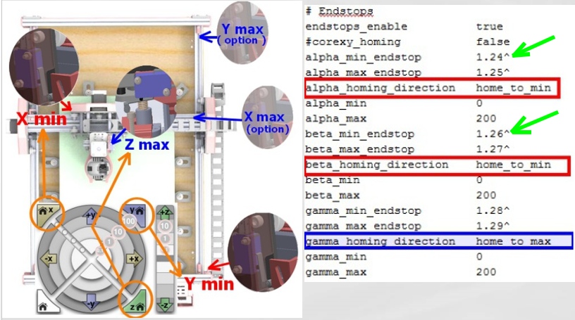
In smoothieboard like arduino board no need prepare pull up resistor for input pin, already have internal board resistor for this fonction.
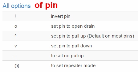
Just activate the « pull up resistor » with option setting in config file
So don’t delete the » ^ » after the number the pin
If you do this the fonction pull up resistor don’t works
In cnc can have endstop min for setting the « 0 » machine and endstop max for when the machine move over capacitie, stop automatically.
The Formosa don’t have max endstop, it’s just a option.
With this way the cabling is more simple, users just need check if the drawing is under the maxi size the machine can cut.
If the machine move over the limit don’t worry just steppers motors loose step but don’t have damage.
Check the correct works of endstop
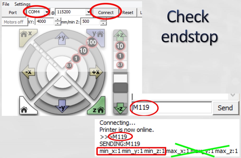
Use M119 command to check if the wiring of endstop is correct
when the endstop is hit, need show 1
When endstop don’t hit, need show 0
If you don’t use xmax ymax … not need there parameters appear can comment
with # in the beginning of line like below to desactivate
alpha_min_endstop 1.24^
#alpha_max_endstop 1.25^
alpha_homing_direction home_to_min
Or use nc in the end of the line like
alpha_max_endstop nc
0 commentaires
Les détecteurs inductifs

I ) Utilisation
Les détecteurs de proximité inductifs permettent de détecter sans contact des objets métalliques à une distance de 0 à 60 mm.
Ils se retrouvent dans des applications très variées telles que la détection de position des pièces de machines (cames, butées, …), le comptage de présence d’objets métalliques.
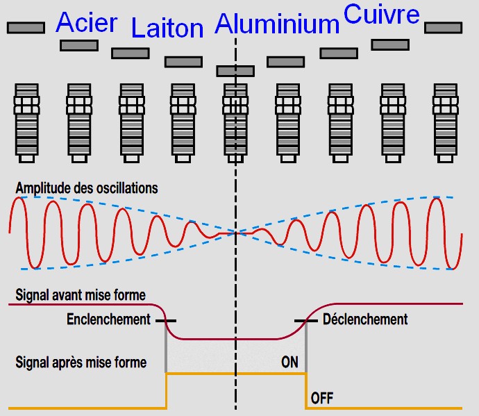
II ) Principe de fonctionnement
Un détecteur inductif détecte exclusivement les objets métalliques.
Il est essentiellement composé d’un oscillateur dont les bobinages constituent la face sensible.
Les capteurs inductifs produisent à l’extrémité de leur tête de détection un champ magnétique oscillant. Ce champ est généré par une inductance et un condensateur montés en parallèle.
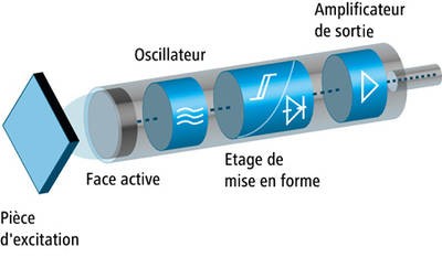
Lorsqu’un corps conducteur métallique est placé dans ce champ, des courants de Foucault prennent naissance dans la masse du métal ; il y a perturbation de ce champ qui entraîne une réduction de l’amplitude des oscillations au fur et à mesure de l’approche de l’objet métallique, jusqu’à blocage complet.
Cette variation est exploitée par un amplificateur qui délivre un signal de sortie, le capteur commute.
III ) Avantages
-
pas de contact physique avec l’objet détecté ( possibilité de détecter des objets fragiles, fraîchement peints )
-
pas d’usure, durée de vie indépendante du nombre de manœuvres
-
détecteur statique, pas de pièces en mouvement
-
produit entièrement encapsulé dans la résine (étanche)
-
très bonne tenue à l’environnement industriel (atmosphère polluante)
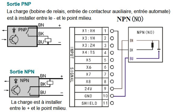
IV ) Branchements / sortie PNP ou sortie NPN
Les détecteurs ou capteurs peuvent être équipés de sorties type PNP et NPN, technique 3 fils, alimentation 30VDC :
-
type PNP : commutation sur la charge du potentiel positif,
-
type NPN : commutation sur la charge du potentiel négatif.
Ces sorties sont typiques des détecteurs inductifs ou photo-électrique.
0 commentaires